*
[Note: The Java Applet for this animation can no longer be run in a web browser. Clicking this link, however, will download to your computer a Java Web Start file named CircularMembraneLaunch.jnlp. This file can launch the animation in a separate window on your computer. Downloading and executing the file may be blocked by local Java permissions, but persevere! You may finally have to launch the file by right-clicking (control-clicking) it and choosing Open, instead of simply double-clicking it.]
*
This animation shows in slow motion the vibration of an ideal circular membrane under uniform tension, fixed at its rim. When struck, a typical membrane of musical interest may vibrate hundreds of times each second, with a motion that even in the ideal case is not periodic. The normal mode frequencies of a real drum head may be quite different from those presented here, because of stiffness and the interaction with the air it displaces during the vibration.
There are two basic sets of displays in the animation. The first set, under way when the applet is launched, shows normal modes of vibration of the circular membrane. Any of sixteen different modes may be chosen from the Mode menu, where they are arranged in order of increasing frequency. Each mode is denoted by a pair of integers as (m, n), where m is the number of nodal lines along diameters of the membrane, and n is the number of nodal circles including one at the rim. The same pair of integers are parameters in the equations describing the motion; these equations are found in the section titled "Technical Details."
The motions of the membrane are shown by a disk representing the membrane, which is colored green where it is in the equilibrium position. The color becomes more yellow where the membrane is displaced out of the screen, and more brown where it is displaced into the screen. Nodal lines may be drawn on the disk if desired. In addition, below the disk there is an accompanying graph of the displacement of the membrane at points along the diameter indicated outside the disk by two white line segments.
The frequency of a normal mode depends on the tension in the membrane and its surface density. Here the frequency of each mode is expressed as a multiple of the lowest-freqency, or (0, 1) mode. To the right of the disk is a linear graph with blue lines representing the frequencies of each of the first 16 normal modes. The frequency of the mode being displayed is highlighted in green. The frequencies are clearly not integer multiples of the lowest mode frequency, and hence motions obtained by combining several modes will not be periodic.
The second set of displays shows motions of the membrane when it is struck at various distances from the center. The motions are computed from sums of the first sixteen normal mode motions, using appropriate relative amplitudes and phases in each case. Expressions for the sums are given below in the section titled "Technical Details." Because there are only 16 terms in the sum, the motions shown can only approximate the expected theoretical motion. Even in this approximation, however, the complexity of the motion is evident.
As before, the motions of the membrane are shown by a disk representing the membrane, which is colored green where it is in the equilibrium position. The color becomes more yellow where the membrane is displaced out of the screen, and more brown where it is displaced into the screen. And, below the disk there is an accompanying graph of the displacement of the membrane at points along the diameter indicated outside the disk by two white line segments. Additional features of these displays include a red dot showing the striking point, several of which may be chosen from the Striking Point menu. Moreover, the graph showing the relative frequencies of the normal modes also shows the relative amplitude and sign of each normal mode in the sum. For these displays there are no nodal lines. Since the motion is not periodic, it is followed for 45 seconds or so and then the animation stops. It may be repeated.
1. At the bottom of the display are two buttons which control the display. Clicking the button labeled "Go/Stop" at any time starts or stops the motion. The button labeled "Nodes" turns on or off nodal lines superimposed on the display of normal mode motions.
2. At the top of the window is a menu bar that affects the display. Available menu choices and their effects are the following:
| Menu Choice | Action |
|---|---|
Drumhead > About Drumhead |
Reveals the name of the author and the year the applet was written. |
Mode > (16 choices) |
Selecting an item from this menu causes the display to show the chosen normal mode motion. Nodal lines may be toggled on or off using the "Nodes" button at the bottom of the window. |
Striking Point > (5 choices) |
Selecting an item from this menu causes the display to show the motion of the ideal membrane when it is struck at the chosen point on the right side of the drumhead. The motion must be started using the "Go/Stop" button at the bottom. The distance of the striking point from the center is expressed as a fraction of the radius of the membrane; the location is indicated by a red dot on the disk. |
Any possible vibration of a linear mechanical system may be expressed as a sum of its normal mode motions, using appropriate relative amplitudes and phases. In a pure normal mode motion, each part of the system moves with simple harmonic motion at the same frequency, and all parts pass through their equilibrium positions simultaneously. Each mode is characterized by its shape, frequency, and damping time. For a general excitation, the actual vibration of a membrane must be expressed as a sum of its normal modes rather than a single, pure normal mode motion. Only if the frequencies of the normal mode vibrations are integer multiples of a lowest frequency will the general motion be periodic.
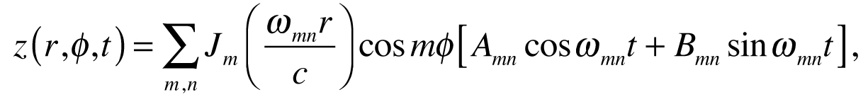
A mathematical expression for the general transverse motion of a circular membrane, fixed at its rim, may be written in cylindrical coordinates as a sum of its normal modes:
where Jm( ) is the mth integer order Bessel function, c is the speed of a transverse wave on the membrane, and
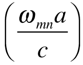
is the nth zero of the mth Bessel function; a is the radius of the membrane. The two constants in each term allow one to adjust the amplitude and phase of each mode in the sum. If ηmn is the nth root of the equation Jm(ηmn ) = 0, then the sum may be rewritten as
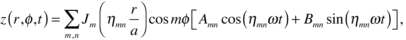
with ω = c/a. Using orthogonality properties of the Bessel functions and trigonometric functions, one can show that for the initial conditions
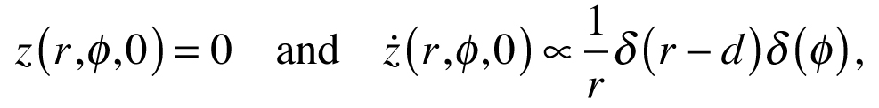
where d is the distance of the striking point from the center and the δ’s are Dirac δ-functions, the constants are
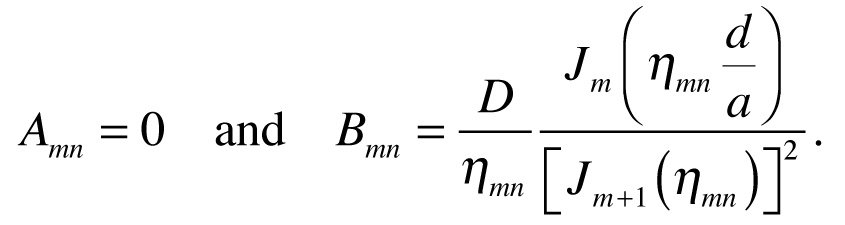
The arbitrary constant D sets the overall amplitude.
(This applet was inspired by similar work of Donald E. Hall reported in "Computer-Animated Illustrations of Vibrations and Waves," Proceedings of the Stockholm Music Acoustics Conference, August 6-9, 2003 (SMAC 03), Stockholm, Sweden.)