| Electricity and
Magnetism > AC Circuits |
DCS# 5L20.20 v.2
|
RLC
SERIES CIRCUIT WITH 4-CHANNEL SCOPE

-
APPARATUS
| function generator |
107-01-A |
| 500 - 6-8 ohm audio
transformer |
214-01-D |
| 60 mH inductor |
214-01-D |
| 1 uF capacitor |
101-09-G4 |
| decade resistor |
214-01-A |
1:1
isolation transformer
|
202-08-B2
|
| 4-channel oscilloscope with
camera |
202-08-B-5 |
DESCRIPTION
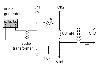
- All four signals - Vin,
VR, VL and VC - can be
displayed
simultaneously.
This setup can be used to show:
resonance in a series RLC circuit.
the broadening of the resonance peak with
increasing
R.
phase relations in an RLC circuit.
the relative sizes of XC and XL
at frequencies above and below resonance.
phase relations in RC and RL
circuits: short
the inductor or capacitor with a wire.
transient oscillations in an RLC
circuit: use
the Pasco function generator/amplifier square
wave output.
RC and RL time constants: short
inductor or capacitor and use square wave mode of function
generator.
- NOTES
- f = [2π√(LC)]-1 = 650 Hz
-
Start with R = 100 ohms.
Note that VR
does not have the same amplitude as Vin
at resonance because of the resistance (6 ohms) of the
inductor.
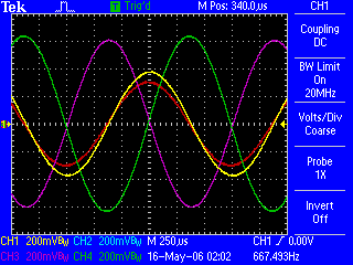
Adjust the camera aperture so that the colors of the traces are
apparent in the projected image.
Color code:
Vin (Ch1) is yellow,
VR (Ch1-Ch2) is red,
VL (Ch3) is purple,
VC (Ch4) is green.


