| Electricity and Magnetism > AC Circuits | DCS# 5L20.xx |
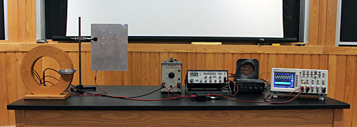
| wavetek function generator | 107-01-A |
| large coil | 101-07-D |
| 3 ft coaxial cable |
015 |
| decade amplifier |
202-08-A |
| mixer / low-pass filter circuit | 202-20-B3 |
| amplifier and speaker | 202-09 |
| oscilloscope with camera | 202 |
| aluminum
plate |
202-18-B |