Oscillations and Waves > Oscillations > Nonlinear Systems
DCS# 3A95.50c

POINCARE SECTION - DISPLAY CASE VERSION

poincare
        display

APPARATUS
Pasco nonlinear oscillator 202-13-F
two DC power supplies, one modified
202-08-D
panel-mounted dial for modified power supply
101-02-E
multimeter
107-01-C
computer with LoggerPro
113B
LabPro interface 107-02-B3
three photogates 107-02-B1
three modular plug to BTA cables
202-14-C1


DESCRIPTION
An aluminum disk with an offset rod is a physical pendulum capable of undergoing chaotic motion.  It is driven by a motor via two springs and damped with a magnet.  A rotary motion sensor and three photogates are used to produce three Poincare plots overlaid on an ordinary phase plot.  The graph shows the pendulum's angular speed vs angular position but, for each Poincare plot, points are recorded only once per drive cycle, when the driver passes through one of the photogates. The Poincare plot is set to refresh every 60 minutes.


NOTES

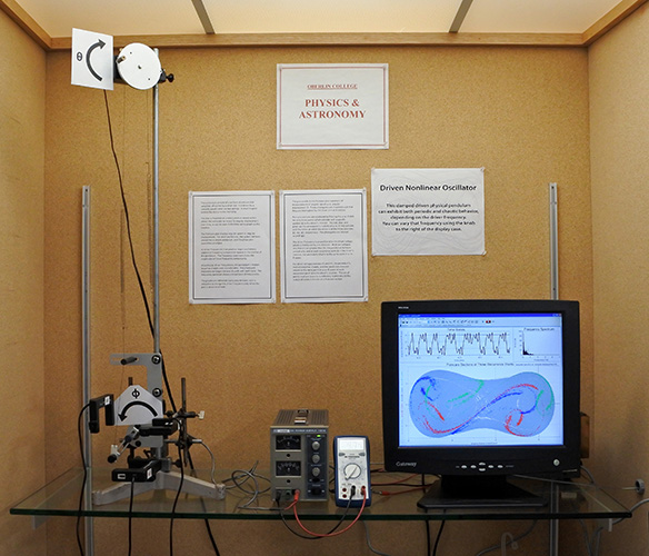
Set up the nonlinear oscillator in the usual manner. Position photogates 120 degrees apart and so the driver passes through each one, once per cycle.

Use the LoggerPro 3 "poincare display" experiment file.

Settings are:
ch1, 2, 3 = raw voltage, to read photogate voltages (note that the photogates are plugged into the analog channels so their voltages can be read)
digital input 2 = rotary motion sensor/angular/high resolution
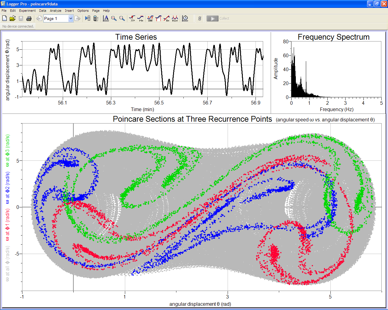
the angular position at constant phase = angular position / photogate state, where photogate state = 1 when the photogate is blocked, and zero otherwise
experiment length =  60 minutes, set to repeat
sample rate = 100 pts/s
graphs:
angular speed vs angular position in gray, with three angular velocity at constant phase vs angular position at constant phase plots overlaid in RGB.
angular position vs time, in strip chart mode, refreshing every minute
FFT, refreshes every 60 minutes.
Zero the rotary motion sensor when the edge mass is at the top of the disk.
The user can adjust the power supply for the motor, which determines the drive frequency. The multimeter allows them to do so reproducibly. The multimeter is powered by the second power supply.

The classroom demonstration version is here.